The software
The firmware and the app are the same whichever path you take. You install them once the hardware is together.
An all-in-one dedicated board by HermitX. Ships with the NFC antenna, a 3 W speaker and an NTAG215 card.
Disclaimer: the HermitX board is a prototype product intended for prototyping and makers. It carries no regulatory certification.
What is fitted on the v4 enclosure today. The list follows the enclosure: changing it reopens several lines, starting with the fasteners and the cutouts.
| Component | Reference | Qty | |
|---|---|---|---|
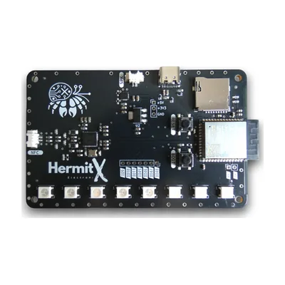 | Development board | ReferenceHermitX N8R8Buy from HermitX | Qty1 |
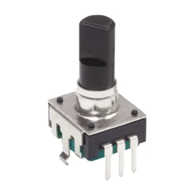 | Rotary encoder | ReferenceBourns PEC12R-3220F-S0024 | Qty1 |
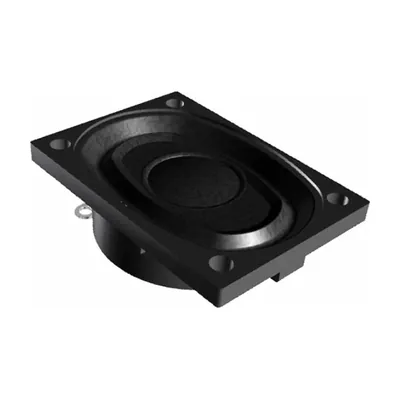 | Speaker | ReferencePUI Audio AS04004PO-2-RThe one that ships with the board is self-adhesive and needs no screw. The PUI replaces it for a fuller sound, with 4 more screws and 4 more inserts, and its oval shape changes the cutout. | Qty1 |
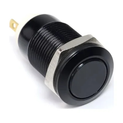 | Push buttons | Reference12 mm metal, momentaryMake sure you take the momentary variant, the kind that springs back on its own. A latching variant only gives you every other useful press. | Qty4 |
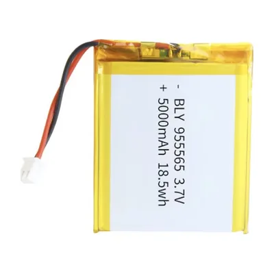 | Battery | ReferenceLiPo 3.7 V 5000 mAh, 955565 format | Qty1 |
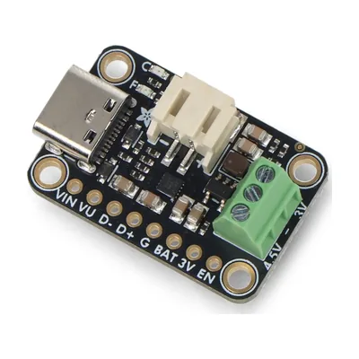 | Charging board | ReferenceAdafruit bq25185 with 5V boost, part 6106Adafruit sells three bq25185 boards that look alike. The pad right before EN tells them apart: 5V on this one, 3V on the buck version, which makes no 5V at all and whose switch would cut nothing. | Qty1 |
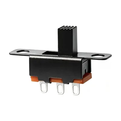 | Power switch | ReferenceSS-12F15, slide, 3 pins | Qty1 |
 | microSD card | ReferenceSanDisk Ultra 32 GB, FAT32Formatted as FAT32, from 8 to 32 GB. | Qty1 |
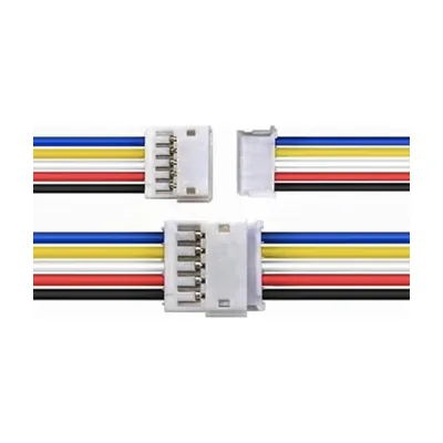 | Encoder cable | ReferenceJST ZH 1.5 mm, 5 pins, 150 mm | Qty1 |
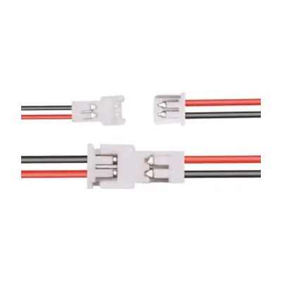 | Power and button cables | ReferenceJST 1.25 mm, 2 pins, 150 mmSame connector for power and for the buttons: mark your harnesses from the first assembly onwards. | Qty5 |
 | NFC cards | ReferenceNTAG215, blank PVC cards | Qty20 |
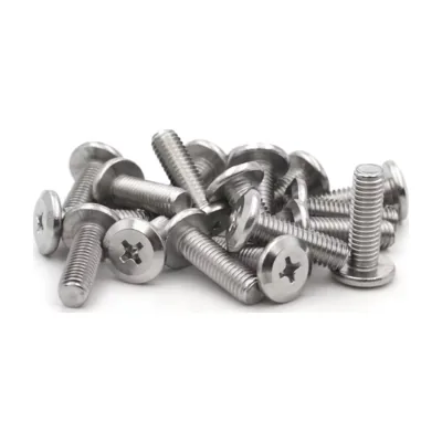 | Internal component screws | ReferenceM2.5 × 5 mm, countersunk head, 304 stainless steelHermitX board, power board, and the PUI speaker if you fit it. | Qty8 or 12 |
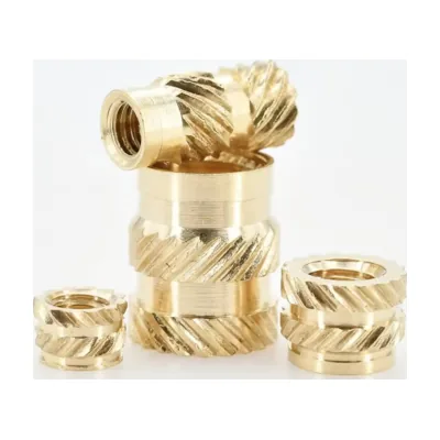 | M2.5 inserts | ReferenceBrass, 3.5 mm outer Ø, 3 mm longOne insert per screw, pressed into the enclosure with a soldering iron. | Qty8 or 12 |
 | Closing screws | ReferenceM3 × 8 mm, countersunk hex socket headCloses the enclosure. | Qty4 |
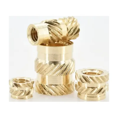 | M3 inserts | ReferenceBrass, 3 mm longOne insert per screw, pressed in with a soldering iron. | Qty4 |
| Printed enclosure | ReferenceFour parts, v4 prototype (see below) | Qty1 |
The NFC antenna ships with the HermitX board, so it has no line of its own. Every thread is a heat-set insert, pressed in with a soldering iron into the housings provided by the print.
Preparing your microSD cardThe cell arrives with its connector already fitted, but its wiring is not standardised: cells shipped with the wires swapped do happen. Before the very first connection, check that the black wire really lands on the minus terminal and the red one on the plus terminal, going by the markings on the charging board and not by the shape of the connector, which fits the same way round either way. Reversed, you destroy the charging board and expose the cell to thermal runaway.
GPIO pinout per peripheral, verified against the firmware code. Logic levels at 3.3 V.
Pick a component to see its wires on the board. Its ? gives the terminal details.
Scroll the board sideways to see all of it.
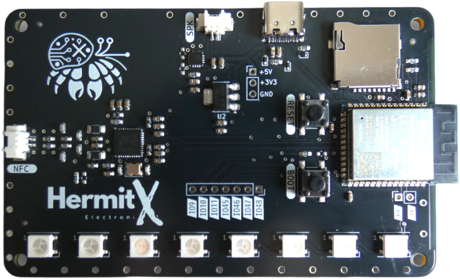
Six vias along the bottom edge: one per button, two for the encoder. The whole board rim is ground; these are simply the ones nearest the controls.
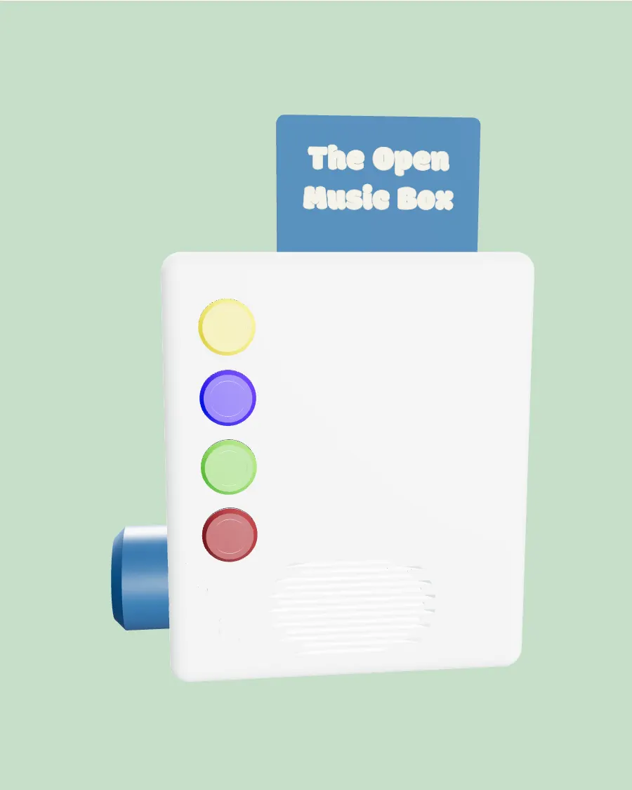
Four parts to print, drawn around the HermitX board for the v4 prototype.
The printable enclosure is designed for the Prototype V4 path. On the DIY path, the enclosure is yours to build. See the DIY path
PLA, 0.4 mm nozzle, 0.2 mm layers
About 11 h 30 for the four parts
Drawn for the v4 prototype. They are published on Printables, Thingiverse will follow.
Published under the CERN-OHL-S v2 licence: you may print, modify, share and even sell what you build, as long as your modified design files stay open under the same licence, with attribution and a link to your source. Read the licence
The firmware and the app are the same whichever path you take. You install them once the hardware is together.
Assemble the parts on a breadboard with Dupont wires. No electronic board fabrication required.